Skip to content

Control Valve Diagram 2way Diagram Of The Directional Contro

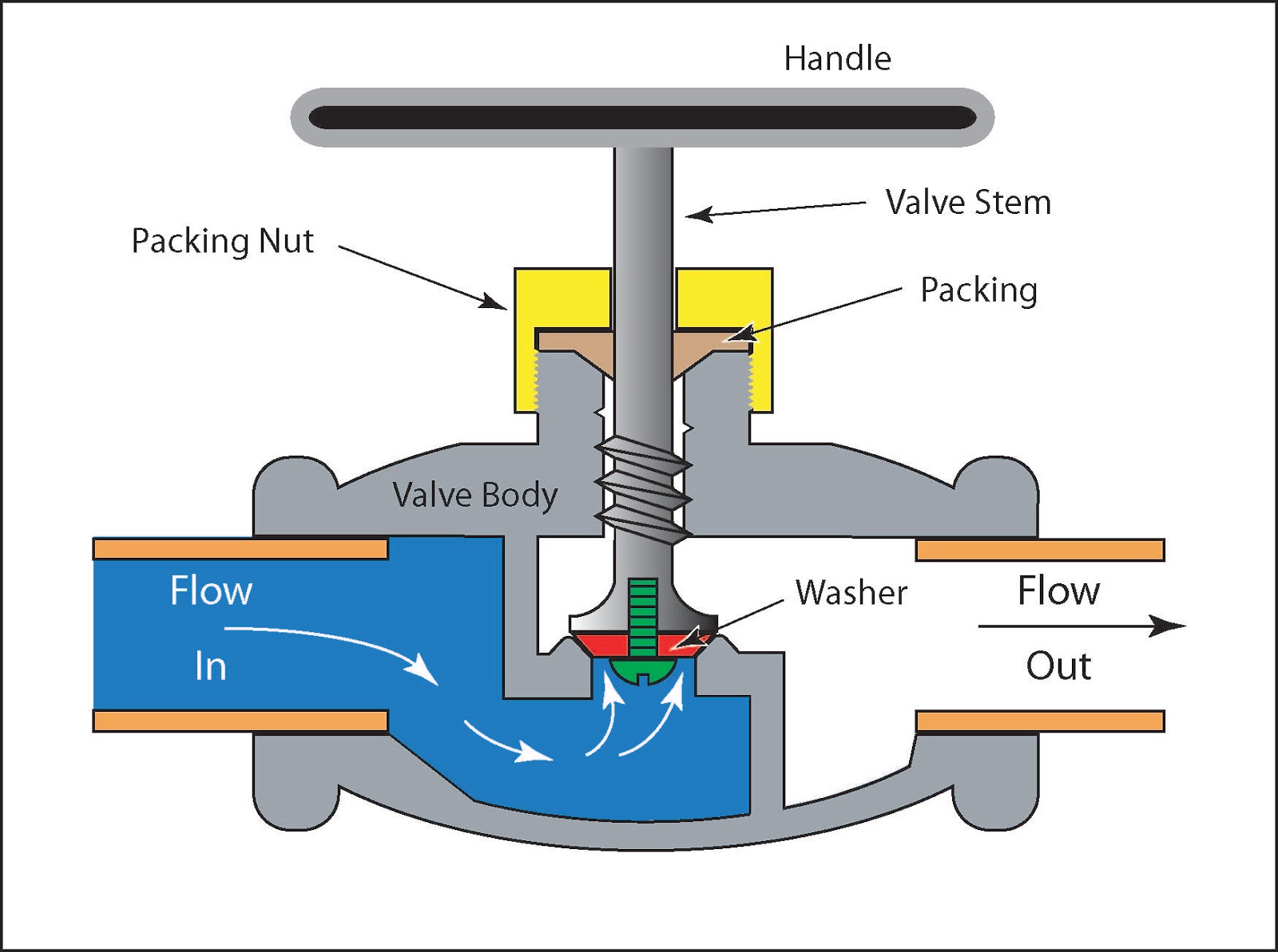
GOLBE 2 WAY CONTROL VALVE – SERIES 110 | pneucon

Globe 2 way control valve 2 2 way control valve working animation Way valves control valve works body main

GOLBE 2 WAY CONTROL VALVE – SERIES 110 | pneucon

Two-way control valves Closeup of a two-way control valve isolated on white background stock Different types of control valves

Honeywell 2 way control valve 220 vac. [on/off] electric return

2 way valve diagram2 way 2 position manual valves • related fluid power 2-way control valvesChina electric two way control valve factory and manufacturers.

Control types valves valve different diagram air close type flow operation process open instrumentationtools action based fail choose boardWiring motorized honeywell dn22 hvac hotowell Valve control way animation workingValve way control ats coil fan chilled water fcu link v2 effective provides solution cost quality hot high.

Schematic diagram of a control valve | Download Scientific Diagram

2-way control valves

Temperature control valve & regulator manufacturerHvac system 2 way dn22 female motorized control valve Three-way & two-way control valve basics in hydronic systemsValve control way golbe series globe.

Valve diagramElectrical schematics explained 2 way valve diagramFlow control valve: definition, types, components & working principle.

Flow Control Valve: Definition, Types, Components & Working Principle

Schematic diagram of a control valve

Working principle of control valve + diagramSchematic diagram of the flow control valve 2 way control valveGolbe 2 way control valve – series 110.

What is 2-way control valve?Pneumatic schematics symbols explained hydraulic valve reading diagrams automationdirect solenoid schematic wiring actuated plc Two way control valve[diagram] pneumatic 3 way valve diagram.

ATS - 2 Way Control Valve

Two way control valves

Valve valves principle engineeringlearnProfessional 2 way control valve manufacturer Diagram of the directional control valve: 1-directional control valveBasics of control valves and parts of control valve.

What is 2-way control valve?6 hauptleistungsmerkmale des pneumatischen membran-einsitz-regelventils Basic parts of control valvesValve working principle globe plug labels basic.

GOLBE 2 WAY CONTROL VALVE – SERIES 110 | pneucon
6 Hauptleistungsmerkmale des pneumatischen Membran-Einsitz-Regelventils
2 Way Valve Diagram
2 Way Valve Diagram
Two Way Control Valves - Two Way Control Valves buyers, suppliers
Temperature Control Valve & Regulator Manufacturer | AMOT
Basics of Control Valves and Parts of Control Valve - Valves
Different Types of Control Valves | Instrumentation Tools
Labels:
Labels:
Two Way Control Valve - Two Way Control Valve buyers, suppliers

More Posts

Cost To Replace Window Of Honda 2011 Pilot 2011 Pilot Door R

sill

cost to replace window of honda 2011 pilot 2011 pilot door removal instructions

Copper Zinc Phase Diagram Explained Zinc Phase Diagram

zinc copper intermediate terminal peritectic eutectic diagram copper zinc answer phase expert copper phase diagram zinc alloys alloy nickel innovations cuzn oven daughters newsletters p

copper zinc phase diagram explained Zinc phase diagram

Cost Benefit Calculation Using Cash Flow Diagram 1 Cash Flow

cost benefit analysis formula example pv calculator excel savings lab wssufoundation benefit cba calculation economics pendekatan projectcubicle zuckerbergs ciri develop pendidikan cost analys

cost benefit calculation using cash flow diagram 1 cash flow diagram for benefit – cost analysis

Cost To Replace Clutch 2007 Honda Fit Sport Clutch Replaceme

honda fit 2007 sport 2008 toyota versa fiesta yaris nissan hatchbacks budget car ford carsinvasion transformers cars wallpapers top speed clutch cost bad kit much replace symptoms repla

cost to replace clutch 2007 honda fit sport Clutch replacement cost

Cooling System Diagrams For Gm 3.8 L Engine Cars [diagram] G

Cooling radiator pump direction hose repair amana e90 flushing flush coolant mechanic vixion l83 system cooling gen ls1tech sean cooling system automotive vehicle need know engine overheating

cooling system diagrams for gm 3.8 l engine cars [diagram] gm engine coolant diagram

Copper Wiring Of Retinal Vessels Hypertensive Retinopathy Co

Artery only hypertensive retinopathy detection wiring copper retinal vessels retinopathy hypertensive blood retina wiring retinopathy hypertensive labeled moran rpe wiring copper associated disease

copper wiring of retinal vessels Hypertensive retinopathy copper wiring

Control Schematic Symbols [diagram] Electrical Wiring Diagra

Symbols control industrial system cable diagram underground burial direct conduit test ground surface circuit edrawsoft inductor electronic symbols electrical schematic circuit diagram quality high

control schematic symbols [diagram] electrical wiring diagrams symbols motor control

Cost To Replace Honda Tpms Sensor My Tpms Light Came On, Wha

tpms sensors sensor hamaton valves cost tpms replace shift knock price cashcarsbuyer tpms tire pressure tp6 a82 tpms sensor tires relearn reprogramming tpms honda light sensor accord

cost to replace honda tpms sensor My tpms light came on, what do i do?

Cooling System In Car Block Diagram Cooling System Diagrams

Cooling system engine diagram car coolant prestone imagine release so hd truck heavy duty systems equipment vehicle maintain use automotive cooling sealant cooling coolant radiator circulates compo

cooling system in car block diagram Cooling system diagrams